Canon 5DS Teardown
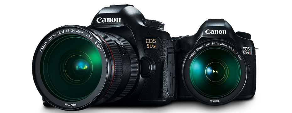
When Lensrentals.com first got the first Canon 5Ds and 5D sr cameras in stock, Aaron and I immediately started screaming that we wanted to take one apart. It turns out we received enough 5Ds cameras to let us have a day with one to do just that. Of course, we don’t expect to find out anything amazing and revealing. We expect it will look pretty much like the Canon 5DIII and 7DII on the inside. But hey, you never know. Plus we’ll be repairing these soon enough, so we might as well find our way around now.
If you want to do some comparisons yourself, you can compare this to our Canon 5D III teardown and Canon 7D II teardown. Or if you’d rather follow along from home with your own 5Ds go grab your screwdrivers and let’s get started!
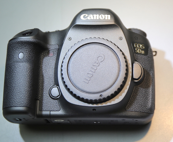
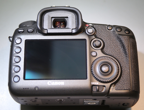
From the outside looking in, there’s not a lot of difference in appearance from the 5D Mk III.
All photographs Roger Cicala, Lensrentals.com, 2015
All photographs Roger Cicala, Lensrentals.com, 2015
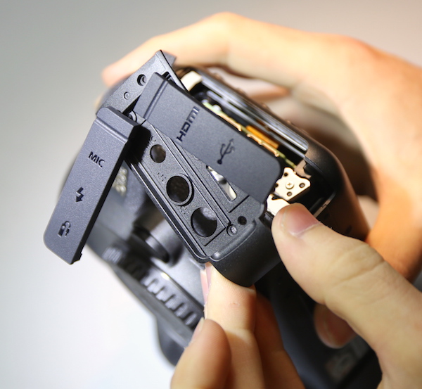
The side panel covering the I/O ports comes off first.
All photographs Roger Cicala, Lensrentals.com, 2015
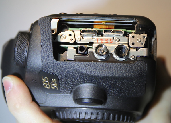
Looking into the camera we see a welcome sight. There are robust metal plates and screws holding the port assembly very firmly. Anyone who has had an HDMI or other port pull off the circuit board when a connected cable gets tugged too hard will appreciate this.
All photographs Roger Cicala, Lensrentals.com, 2015
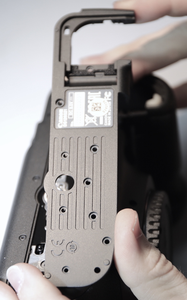
The bottom plate is removed next.
All photographs Roger Cicala, Lensrentals.com, 2015
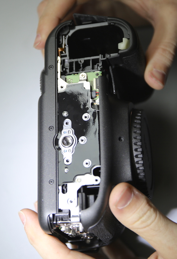
The tripod base is now exposed. It is supposed to be more robust than previous 5D cameras but we can’t tell a lot from here, although there do seem to be more screws holding it to the chassis than with the 5D Mk III.
All photographs Roger Cicala, Lensrentals.com, 2015
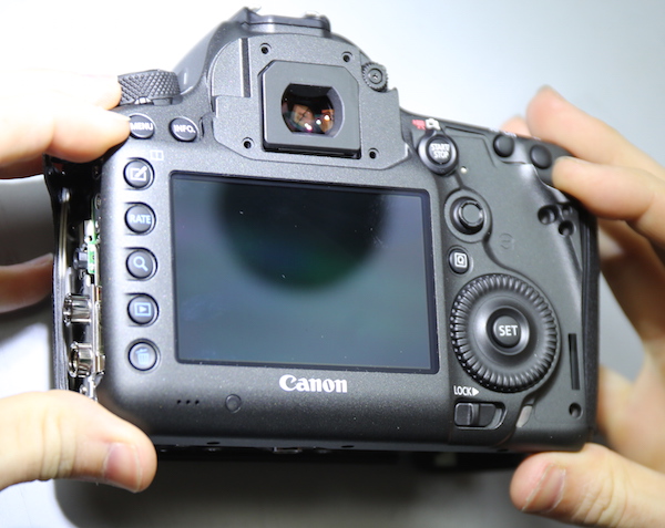
The back cover assembly removes in an identical manner to the 5D Mk III.
All photographs Roger Cicala, Lensrentals.com, 2015
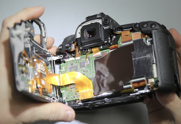
There is a slightly different connector from the back assembly to the PCB.
All photographs Roger Cicala, Lensrentals.com, 2015
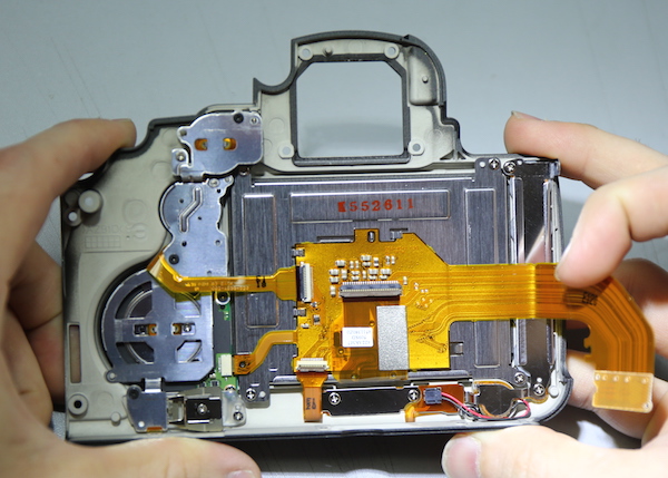
And the back panel assembly has only minor differences from the 5D III. One worth noting is the aluminum LCD backing plate is stronger with some stamped strengthening areas pressed into it. In previous 5D cameras the LCD could be pressed down into the camera pretty easily because the backing plate was pretty thin.
All photographs Roger Cicala, Lensrentals.com, 2015
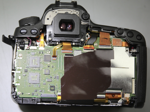
Internally, the camera looks a little different because the PCB is partly covered with a thick, plastic adhesive sheet rather than the thin sticky-taped vinyl we usually see.
All photographs Roger Cicala, Lensrentals.com, 2015
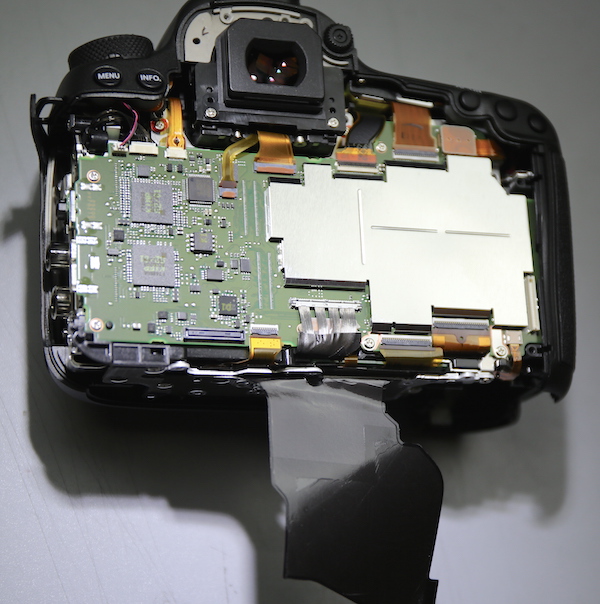
This is the material used in the 7DII, and is a lot easier to work with than the 5DIII’s flimsy vinyl tape. It doesn’t make a bit of difference to anyone who doesn’t repair cameras, but I do repair cameras and so I was pleased. This is much easier to peel up without tearing.
All photographs Roger Cicala, Lensrentals.com, 2015
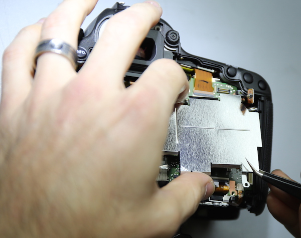
The electrical shields are removed easily.
All photographs Roger Cicala, Lensrentals.com, 2015
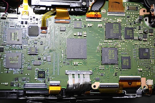
And now the PCB and most of the camera’s chips are exposed.
All photographs Roger Cicala, Lensrentals.com, 2015
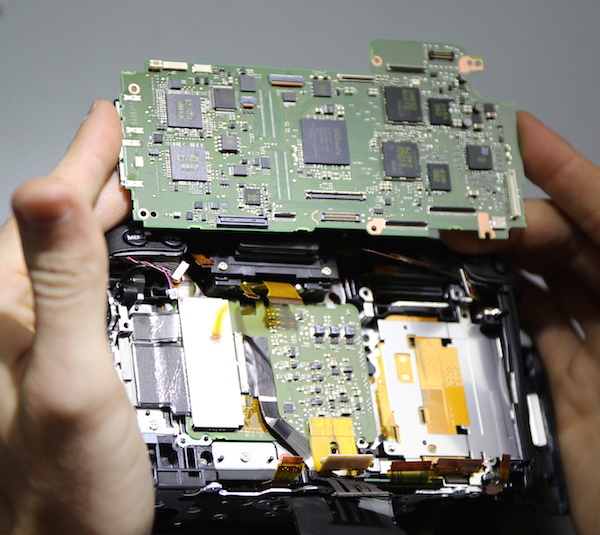
Unhooking a LOT of flexes and taking out a few screws lets us remove the PCB. One thing you probably didn’t notice, but that made us weep with joy: the I/O ports are NOT soldered to the PCB. They are on a separate board that we’ll show you later. This is a big thing, because now if you pull one of the I/O loose, it no longer means a PCB replacement is necessary.
All photographs Roger Cicala, Lensrentals.com, 2015
For you chip hunters, here’s the PCB out of the camera.

All photographs Roger Cicala, Lensrentals.com, 2015
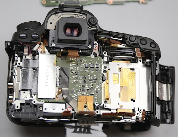
Looking beneath the PCB in the camera body, we can see the sensor’s circuit board in the center and the CF card assembly over on the right.
All photographs Roger Cicala, Lensrentals.com, 2015
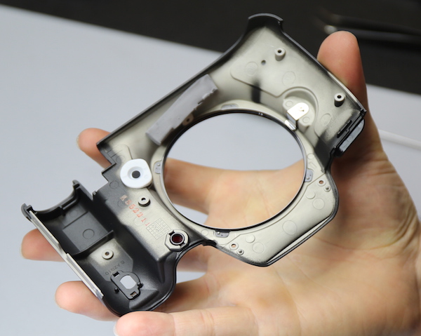
Next step in stripping the camera is removing the front plate, which is quite straightforward.
All photographs Roger Cicala, Lensrentals.com, 2015
With the front, sides, bottom and back removed, there’s only one more screw left before we can remove the top plate.
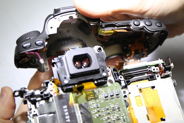
The top plate itself isn’t much different than what we’ve seen in numerous other Canon DSLRs.
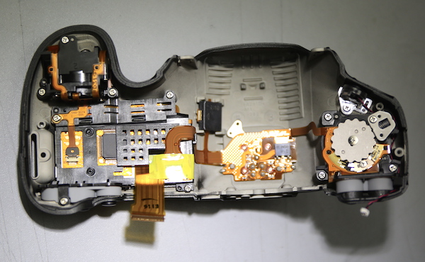
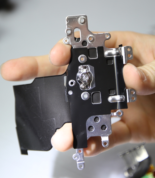
And finally the bottom tripod mounting plate was removed.
All photographs Roger Cicala, Lensrentals.com, 2015
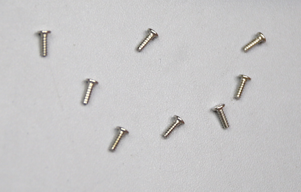
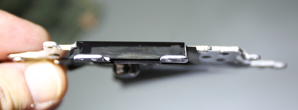
We had been told the tripod plate was more robust than in the 5DIII, and that certainly is true. It’s mounted to numerous chassis points with a total of 8 very long screws. I don’t usually show pictures of screws, but theses are serious things, way longer than what we are used to seeing mount tripod plates to cameras. And while a camera breaking at the tripod mount is untypical, it’s nice to see that these cameras are getting more and more robust.
All photographs Roger Cicala, Lensrentals.com, 2015
The side view shows the metal in the plate is thicker than we’re used to seeing, too.
All photographs Roger Cicala, Lensrentals.com, 2015
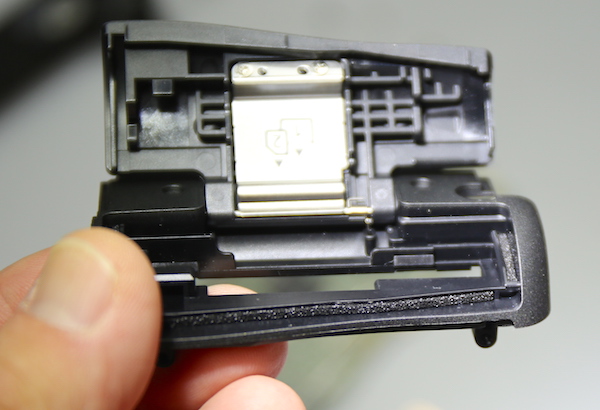
Finally we took off the memory card door. It didn’t have to wait until last, but we like to do it that way because of the door-shut sensor underneath; it’s easy to break and breaking it results in major problems.
All photographs Roger Cicala, Lensrentals.com, 2015
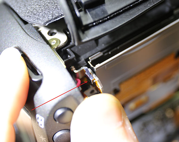
Here is the paper-thin door shut sensor, which fits through a little slot in the memory card door. Bend it and the camera thinks the door is open and won’t power on.
All photographs Roger Cicala, Lensrentals.com, 2015
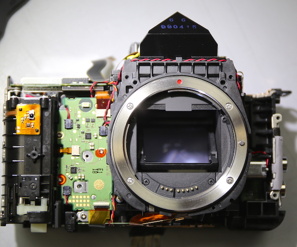
With all the external covers and cases off we can take a look around the insides of the camera a bit. The overall front view gives a nice look at the pentaprism up on top showing you just why SLRs all have that hump in the middle. On the left is the battery housing PCB and battery housing.
All photographs Roger Cicala, Lensrentals.com, 2015
One thing we weren’t thrilled about is the plastic lever on the metal lens-release-locking pin. It may be just fine, probably is just fine. But my inner-paranoid repair guy comes out and thinks ‘if that plastic lever comes loose from the pin, a lens is locked on to the camera body’.
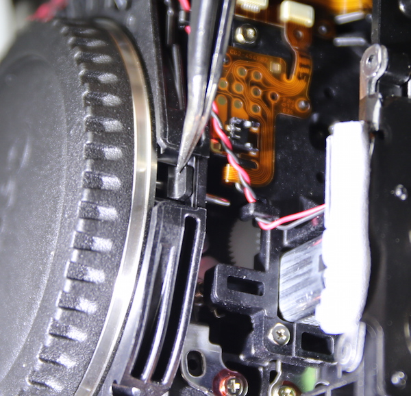
All photographs Roger Cicala, Lensrentals.com, 2015
Going underneath the camera, we can get a good look at the AF sensor. Well, not the sensor itself, the housing of the AF sensor (red arrow). The housing is black and difficult to see, but you can see some white marks it. Also note the adjustment screws and the thick glue used to keep it locked in place after it was adjusted at the factory.
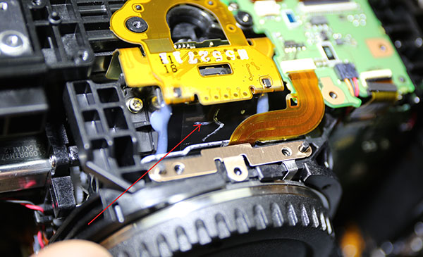
All photographs Roger Cicala, Lensrentals.com, 2015
While we’re looking around, I should probably mention weather sealing because many of you are fascinated by it. Canon presents the 5Ds and 5D sr as studio cameras and the weather sealing clearly isn’t as robust as that we saw in the 7D Mk II, but it’s still pretty good, particularly around the doors. You can see foamed sealing around the memory card door in an earlier image. There’s similar sealing around the battery door on both sides. We didn’t see any rubber gaskets around the top assembly, rear assembly, etc.
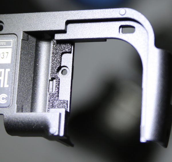
All photographs Roger Cicala, Lensrentals.com, 2015
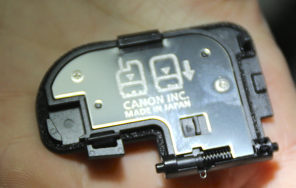
All photographs Roger Cicala, Lensrentals.com, 2015
The bottom line is this is standard weather sealing. Would I take it out in the rain? Hell no. But I wouldn’t take any other camera out in the rain without plastic bags over everything, either. I don’t trust ‘weather sealing’ and neither do the manufacturers. Otherwise their warranty would cover water damage, and it doesn’t.
We also wanted to take a closer look at the I/O ports on this camera. Most of you have probably never had a problem with this, but having to replace a PCB because an I/O port has been yanked off is becoming more and more common as people attach more external devices to their cameras.
I’m most impressed by Canon’s approach to this. The ports are all on a separate board, connected by wires to the main PCB. So a broken I/O port means simply replacing this board.
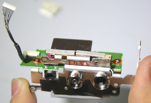
All photographs Roger Cicala, Lensrentals.com, 2015
The removal shows just how seriously Canon has planned this out. The board is strongly braced directly to the camera chassis at several places, so the ports are much less likely to bend and tear off in the first place. If you look back at our 7D Mk II teardown you can see the I/O ports were strengthened and partially moved off of the PCB; the 5Ds cameras improve this even further.
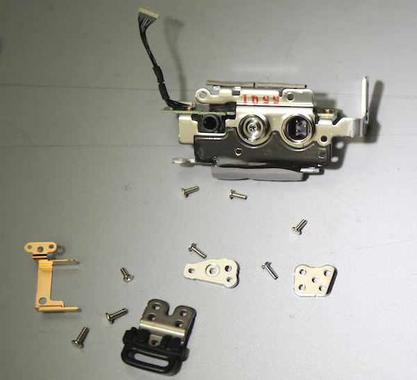
All photographs Roger Cicala, Lensrentals.com, 2015
As an aside, removing the I/O assembly, its covering tapes, and the metal shield uncovers the four Analog Devices A/D converters.
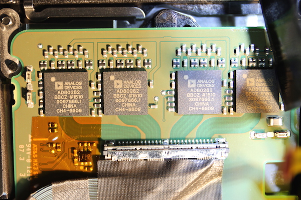
All photographs Roger Cicala, Lensrentals.com, 2015
We did take out the CF card assembly, which is thankfully on a separate board. (Some cameras solder this to the PCB, too, so when a pin is bent or broken a PCB replacement may be needed.) The SD card slot is soldered to the back of the PCB, but SD card slots are far less likely to break than CF slots are.
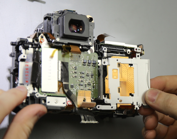
All photographs Roger Cicala, Lensrentals.com, 2015
With everything removed we could get a glimpse at the edges of the image sensor around its circuit board (the green board in the center of the image above).
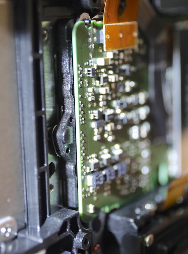
Taking the image sensor and mirror box out will have to wait for another day, I’m afraid. Stock is still short and this camera had to be reassembled, tested, and shipped out today. Removing the sensor-mirror box assembly might have put things out of alignment and while we are gutsy, we aren’t dumb enough to be certain we could have gotten that all corrected in another hour or two.
Summary
Outside of the stuff we already know about the new Canon cameras, there were not many surprises looking inside, and the few surprises we had were positive. There was Canon’s usual very clean design and layout. There were incremental improvements in the engineering, like the separated I/O system, more robust tripod mount assembly, and improved inner tapes and shields. I have a little concern about the lens release pin, but it probably will not be an issue. After all, I’m known to be paranoid.
When we get more stock and demand slows down we’ll pull the sensor out of one for closer examination, but that will have to wait a month or two.
Roger Cicala and Aaron Closz
Reposted with permission from Lensrentals.com, June, 2015


